In this article, I will give you an idea how to create a Deployment Diagram for Banking System 2022. Aside from this idea, you can get the Banking Deployment Diagram, which will be useful for your DBMS studies.
The Banking System Deployment Diagram serves as an example of the class linkages and source code dependencies in the Unified Modeling Language (UML). An object, which is a particular thing in a program or a piece of code that represents that object, has methods and variables that are described by the object’s class.
Deployment Diagram for Banking : Project Details
The table shows the most important parts of the Banking System. It gives a quick summary of what the project is about.
| Name: | Banking System Deployment Diagram |
| Abstract: | The Banking System Deployment Diagram represents the physical structure of the project. It reveals the software and hardware included for the banking system to work properly. |
| UML Diagram: | Deployment Diagram |
| Users: | Bank Admin, Bank Owner, and Clients |
| Tools Used: | Diagraming Tools that have UML Deployment Diagram Symbols |
| Designer: | SourceCodeHero.com |
Banking System Deployment Diagram Description
Deployment diagrams show how software and hardware work together to make sure the Banking works right. It does a good job of explaining how software works with hardware. This also helps figure out which pieces of software a certain kind of hardware needs.
A UML deployment diagram is used by Banking System to show how the software should be deployed. It makes clear how links (nodes) talk to each other, which helps the project work the way it was designed to.
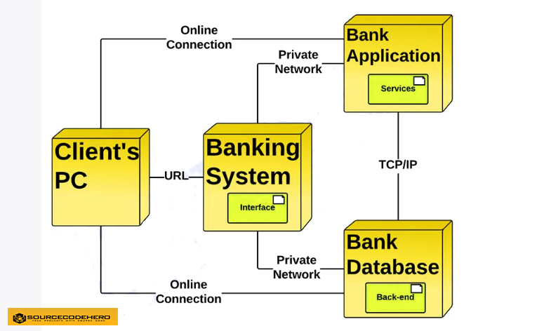
Deployment Diagram for Banking System
In UML, deployment diagrams show how the Banking system’s software and hardware work together and where the processing happens.
- Artifact – A product made by software is shown by a rectangle with the name and word “artifact” inside two arrows.
- Association – A line shows that there is a message or other kind of communication between two nodes.
- Component – A component is a square with two tabs that shows a piece of software.
- Dependency – A dashed line with an arrow at the end shows that one node or piece depends on another.
- Interface – A circle shows that there is an agreement. Those things that make up the interface have to do some kind of work.
- Node – A piece of hardware or software is represented by a three-dimensional box.
- Node as Container – This is a node that contains another node, like nodes that hold components.
- Stereotype – A device that is inside of the node and is shown at the top of the node between two arrows.
How to make Deployment Diagram for Banking?
Time needed: 5 minutes
This is the steps on how to create deployment diagram for Banking System. In creating this deployment diagram, we used lucidchart.com
- Step 1: Open your Diagramming tool.
You might see a blank page when you open the tool. It has a few buttons at the top and bottom of the page. You can use any tool that helps you feel good. You can choose which diagram to use. You can draw it manually if you like.
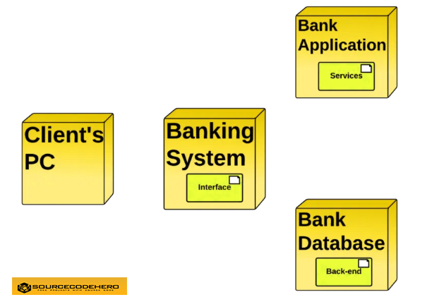
You can use any tool to make a diagram as long as it has the symbols or elements you need for the deployment diagram. These are the artifacts, associations, components, dependencies, interfaces, nodes, etc. This is so that your diagram will be full and clear. - Step 2: Finalize the Nodes (Software and Hardware)
In the second step of making a deployment diagram, you finalize the hardware and software requirements for the project. Then you’ll carefully put them in place, leaving space for the arrows that will link them. This step will look like this.

- Step 3: Map the Connections between Nodes
Lastly, you will draw the arrows that show how the nodes are linked to each other. These links should be labeled so you can tell what kind of relationship they use between nodes. The common connections are made through networking and other means.
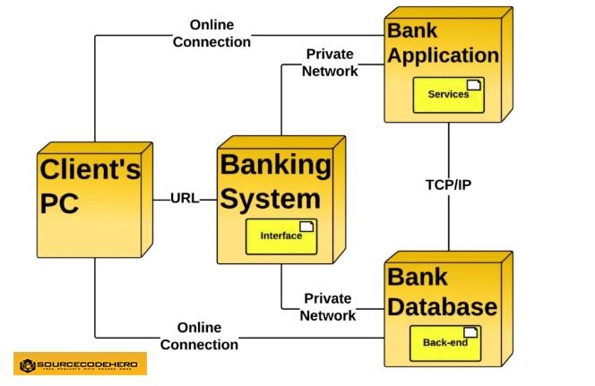
Deployment Diagram for Banking System
Benefits of UML Deployment Diagram
- It aids in the visualization of the various aspects involved.
- Aids in a more accurate description of all the hardware elements used by software components.
- It clarifies the description of the runtime involved in processing nodes.
- Provides hardware specified details for a distributed application.
- Helps in modeling the system’s hardware topology.
- It aids in the modeling of inserted or included software.
- Provides more information on the hardware system.
- Reverse engineering is made easier using the UML deployment diagram.
Conclusion
In conclusion, we have discussed about Deployment Management System for Banking System, its project details, and description. We have shown an example of a deployment diagram for Banking System and lastly we explained what is Banking.
Related Articles
Inquiries
If you have inquiries or suggestions about Deployment Diagram for Banking System, just leave us your comments below. We would be glad to hear to concerns and suggestions and be part of your learning.
Keep us updated and Good day!