In this article, I will give you an idea how to create a Component Diagram for Hospital Management System 2022. Aside from this idea, you can get the Hospital Management, which will be useful for your DBMS studies.
The UML component diagram of a online shopping is used to show how the parts of the online shopping work together to do their job well. This diagram of the software’s components shows how they are put together and how they depend on each other. It shows the parts of the online shopping from a high level.
Component Diagram for Hospital Management System: Details
| Name: | Hospital Management System Component Diagram |
| Abstract: | In object-oriented programming, a senior developer can use the component diagram to group classes together based on their common purpose. This way, the developer and others can see how a project is progressing at a high level. |
| UML Diagram: | Component Diagram |
| Users: | Hospital Admin, Physicians, Nurses, and Patients. |
| Tools Used: | Diagraming Tools that have UML Component Diagram Symbols |
| Designer: | SourceCodeHero.com |
Benefits of using Component Diagram
Even though it looks complicated, the component diagram is a key part of building your system because it shows how everything works together. The design of the hospital management component diagram has the following benefits:
- Shows how the system actually looks.
- Pay attention to the system’s parts and how they work together.
- Pay attention to how the service behaves when it comes to the interface.
Characteristics of Component Diagram:
- They are used to describe systems with a service-oriented architecture in component-based development.
- Displays how the code looks.
- It can be used to draw attention to how the parts fit together while hiding the details.
- Help stakeholders understand how the system being built works and how it will be used.
What is Hospital Management System Component Diagram in UML?
In the Unified Modeling Language (UML), a component diagram shows how parts are connected to make bigger parts or software systems. They are used to show how any kind of system is put together.
The software solution is made to meet the needs of the system, the users, the content of the operation, and the task that will be done.
How to make Component Diagram for Hospital Management System?
Time needed: 10 minutes
This is the steps on how to create component diagram for Hospital Management System. In creating this deployment diagram, we used lucidchart.com
- Finalize the Function and Processes of the Software
The first step in making a component diagram is to decide on all of the software’s processes and functions. This activity will help programmers figure out what they need to do to finish managing a hospital. Then, the finalized processes or functions will be the basis for designing the system’s component diagram.
- Put the Components included
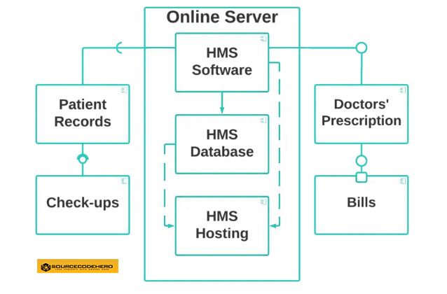
A part of a system that makes sense in terms of logic is called a component. It’s not quite as concrete as classes. You can tell a component from a class by the tabs or the word “Component” written on top of its name.
 The component symbol is used for a person or thing that needs to fulfill a stereotype function. Through interfaces and other parts, it gives and takes behavior. Components can be put together into nodes or other components, but there can only be one component at a time.
 - Add the Dependencies (Ports and interfaces)
One part needs the information and services of another part, but not always the other way around. This is called a dependency. You should make a link between two parts to show that one depends on the other.

The port of a component shows where the component and its environment come together. In this picture, ports are shown on the sides of classifiers as small squares. It is made when something needs something else to work. The “include” statement for the part that needs the other part is in the make file for that part.
Interfaces show how parts are wired together and how they work together. The assembly connector lets you connect a part that needs a certain interface to another part that already has that interface. It looks like a semi-circle and a line.
A component list shows which interfaces a component can use or implement. Interfaces are also needed for components to do their jobs. It’s part of a system that keeps what’s inside safe. They are the parts of a system that make sense and are a big part of how a system works.
 The component symbol is used for a person or thing that needs to fulfill a stereotype function. Through interfaces and other parts, it gives and takes behavior. Components can be put together into nodes or other components, but there can only be one component at a time.
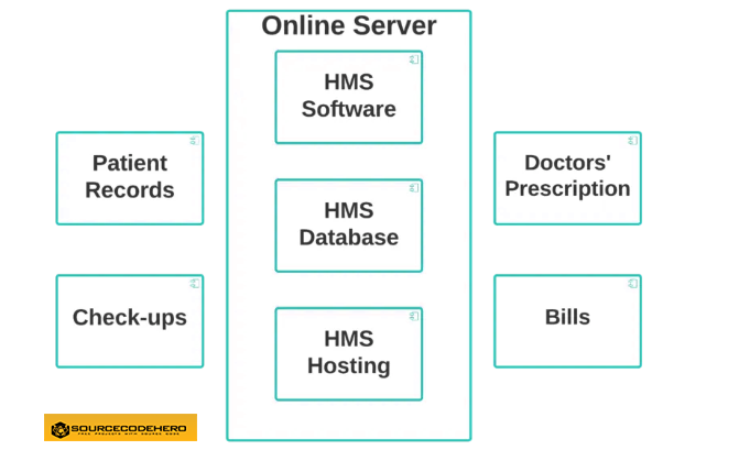
The Component Diagram of Hospital Management System
This component diagram of hospital management system shows that each hardware and software node is made of. The component diagram for the hospital management system is shown in detail in the diagram below.
Conclusion
To summarized, we have discussed about Component Diagram for Hospital Management System, its project details, characteristics, benefits and description. We have shown an example of a component diagram for Hospital Management and lastly we explained what is Hospital Management Component Diagram.
The Hospital Management System needs a diagram to show the classes that are needed to get the result that is wanted. It is used to model the parts of the system, show how they relate to each other, and describe what those parts do and what services they offer.
Related Articles
- Deployment Diagram for Hospital Management System
- Class Diagram for Hospital Management System
- Hospital Management System Use Case Diagram
- Sequence Diagram for Hospital Management System
Inquiries
If you have inquiries or suggestions about Component Diagram for Hospital Management, just leave us your comments below. We would be glad to hear your concerns and suggestions and be part of your learning.
Keep us updated and Good day!